
Part One: The "Basics"
This information is intended to give one a better understanding of how Centralized Traffic Control (CTC) operates. All information is of a general description and does NOT focus on one particular prototype, but instead on standard practices used throughout the railroad industry. CTC and signaling in general is such an involved subject, that I will try keeping simple, yet I do not want to leave out any key points. Hope you enjoy this information and happy model railroading!
An early signal engineer once said, “The art of signaling may be quite truly termed the art of saving seconds safely.” You could say that the railroad industry took this idea and ran with it purchasing CTC for much of their busy mainlines.
Beginning in the mid-30’s, the railroads continued construction from one division to another as time and money became available. The priorities were established according to traffic density and savings. On average CTC saved trains 42 seconds per mile and permitted passenger trains to make up lost time without delaying other trains. Compared to timetable and train order operations this was a vast improvement, not to mention CTC greatly reduced the danger of human error. The economics alone of eliminating telegraph offices and interlocking operators made it justifiable to install CTC.
CTC is defined as “a block system under which train movements are authorized by block signals whose indications supersede the superiority of trains for both opposing and following movements on the same track.” CTC provides centralized control for signals and switches within a territory of defined limits, controlled from a single control console known as a control machine. Because the distance between the control machine and the field locations in CTC territory usually extends a number of miles, the system is controlled by code and carrier equipment. A direct-wired arrangement would require one pair of wires for each controlled signal and switch within the CTC territory, and would not be economical. The code and carrier system allows the CTC system to operate over only two line wires, known as the code line. This circuit is the most important pair of wires on the pole line. More so than the dispatcher’s phone circuit and is the first to be repaired if major damage to the pole line occurs. The control machine provides a means for the dispatcher to monitor wayside conditions and to initiate the control codes thru push buttons and levers. The control codes are sent to the field equipment via the code line to control the corresponding signals and switches.
Each end of a siding controlled by the dispatcher is called an interlocking. In contemporary railroading this is called a control point (CP). The definition of an interlocking is: “An arrangement of signals and signal appliances so interconnected that their movement must succeed each other in proper sequence and for which interlocking rules apply.” Each signal governing entrance to an interlocking is called an interlocking signal or home signal. These signals display stop (rule 292) as their most restrictive indication.
When a less restrictive indication than “stop” is displayed, a signal is said to be “cleared.” The track between the outer opposing signals is referred to as the interlocking limits. The detection circuit (track circuit) within the interlocking limits is known as the detector track circuit. The dispatcher calls this same circuit the O.S. section, O.S. meaning “on sheet.” When this circuit becomes occupied by a train the dispatcher will show on his train sheet that this train is by the location that corresponds with that particular circuit.
Not all signals in CTC territory are controlled by the dispatcher. Intermediate signals (signals with number plates) generally govern movements between interlockings and are commonly spaced at one train length apart. These signals are usually operated automatically within the CTC system and their aspect determined by train location and track condition. Signals controlled by the dispatcher do not have number plates and are two or three unit signals. Each signal unit is commonly referred to as an arm. This comes from the early days when the blade on a semaphore signal was called an arm. Each signal unit may display one, two or three colors. Some people call each color in a signal unit an aspect; do not be confused: an aspect is the appearance of a signal conveying an indication either by one color being displayed or by a combination of colors being displayed. Each color should be referred to as a light. Signal units that display only one color are called marker lights.
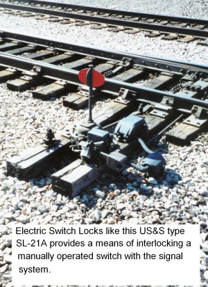
Signals in CTC territory controlled by the dispatcher have the prefix on the control machine L or R. This comes from the days when the operators were located in cabins along the tracks. As you might imagine L signals were to his left and R signals were to his right. When CTC began to be installed, L signals became westbound and R signals became eastbound. Most railroads list the tracks in their timetables as east and west, even though they may geographically run north and south. In the event that the tracks do run north and south, north becomes west and south becomes east. In conjunction with the L or R prefix signals are numbered evenly, 2, 4, 6, 8, etc. For example, a westbound signal at the east end of the siding could be labeled L88. The eastbound signal would be R88. Switches and electric locks are labeled with odd numbers, 1, 3, 5, 7, etc. so the switch at the east end of the siding would be 87.
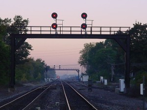
Figure 1 shows a standard layout of signals at both the east and west ends of an interlocked siding in CTC territory. The dispatcher controls all signals and switches at this type of location.
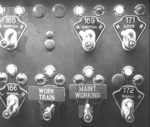
Figure 2 shows the standard arrangement of signal units for this type of location. Home signal R174 governs eastward movements over the power switch in the facing point direction either across the main track or into the siding. This signal is known as the facing-point signal. The top or (A) unit has three-colors; green, yellow, and red. This unit governs eastward main track movements through the interlocking and to the next governing signal. The lower or (B) unit has two-colors; yellow and red. This unit governs eastward movements through the interlocking from the main track into the siding. Home signals L174 and LB174 governs westward movements over the power switch in the trailing point direction. Both signals are referred to as the trailing point signals. Both signals govern westward movements through the interlocking and to the next governing signal. Signal L174 governs this movement across the main track. The (A) unit of this signal is again a three-color unit; green, yellow, and red and like R174 it also governs main track movements, but in the westward direction. Signal LB174 governs the trailing point movement from the siding to the main track. This signal is of the dwarf type. A dwarf signal is a low signal used in yards or at a siding or where clearance restricts the use of a high signal. This signal also has three colors; green, yellow, and red. The other end of the siding would have the identical arrangement of signal units, but using the next couple of numbers higher in the sequence. The prefix L and R is also reversed to show the proper direction at the East end.