
Part Two: Clearing a Signal at an Interlocking
Let’s now look at the requirements for clearing a signal for any given route through an interlocking. I will list each condition that the signal system will check. This should help in setting up your own signals to operate more like the prototype. Looking at Figure 1, let’s assume that there is a westbound train approaching signal L88 at the east end of the siding. The dispatcher has decided that this siding will be the best place for the westbound to meet an eastbound. The dispatcher from his control will send out the control code to reverse switch 87. Before switch 87 will throw the signal system will check three conditions:
1. No train is within the interlocking limits (occupying the detector track circuit) – this protects against throwing the switch under a train.
2. No home signals at this interlocking are cleared for a route over the switch.
3. Against throwing for a predetermined time delay, after a home signal governing movement over the switch is cleared, and then put back to stop by the dispatcher.
Condition #3 is known as “time locking”. Time locking protects against the dispatcher clearing a signal for an approaching train, then putting the signal back to stop and changing the route. When the dispatcher manually puts the signal to stop, the signal system will make him wait a set time before he can change the route or clear the opposing home signals. This time interval is to allow the approaching train sufficient time to stop safely before his original route is changed. The formula that we use on the railroad to determine this time interval takes into account track speed, curvature, and other pertinent train handling factors. It can be as short as two minutes and as long as eight minutes. Considering that most modelers run their railroads using a fast clock, running eight or even two minutes of time for time locking would not be practical. My experience has been a delay of one minute is sufficient and seems to work quite nicely. You may find for your railroad you want a longer or shorter time interval, or you may not want to emulate time locking at all. If any of the above three requirements are not met, the switch is locked and cannot be thrown under power:
After switch 87 has thrown to the reverse position it will indicate to the control machine that it has responded and is now in the reverse position. Next the dispatcher will send out the control code to clear signal L88 for the westbound to enter the siding. Again the signal system will check several conditions.
1. No train is occupying the detector track circuit or the block protecting the siding. This block extends between signal LC82 and RC88.
2. That home signal RC88 is not cleared for an eastward movement and that this Signal is not in the process of running time for time locking.
3. Note that this condition is only checked if switch 81 is in the reverse position. No train is occupying the detector track circuit at the west end of the siding and that signal R82 is not cleared or running time.
4. Switch 87 is in the reverse position.
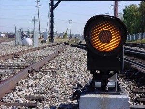
If all these conditions are met signal L88 will display a red over yellow aspect and the field equipment will indicate to the dispatcher that this signal is now cleared. The red over yellow aspect is a restricting indication (Rule 290). This signal informs the engineer that he may proceed not exceeding 15 MPH and prepared to stop short of an obstruction, or anything else that may require him to stop. Aspects and indications will be discussed more thoroughly in part four of this series.
Now the dispatcher must clear the appropriate signal for the eastbound train. Assuming switch 81 at the west end of the siding is in the normal position, the dispatcher will send out the control code to clear signal R82. The signal system will check the same conditions that were previously checked to clear signal L88 but, for the route signal R82 will be governing (i.e. down the main track):
1. No train is occupying the detector track circuit at this interlocking and the block between signal L82 and R88 is not occupied.
2. Signal L82 is not cleared for a westbound movement or in the process of running time.
3. Switch 81 is in the normal position.
Considering that switch 87 at the east end of the siding is already in the reverse position to allow the westbound to enter the siding the signal system knowing this will not check signal L88 or the detector track circuit at the east end. Once these conditions have been checked signal R82 will display a yellow over red aspect. The yellow over red aspect is an approach indication (Rule 285) and informs the engineer that he may proceed not exceeding 30 MPH and to be prepared to stop at the next signal (i.e. signal R88). The dispatcher has now successfully set up a meet between two trains. All of this took him less than one minute to do. This is what makes CTC so efficient. The dispatcher has no train orders to write and relay to a telegraph operator, who then has to hoop them up to the appropriate train. Also each train would then have to stop and throw the appropriate switches by hand.
After the westbound train has passed the “cleared” signal (i.e. signal L88), it moves into the interlocking limits, it is now occupying the detector track circuit. The signal now automatically returns to stop, and the field equipment will indicate to the control machine that the detector track circuit is occupied and that the home signal is at stop.
Once the last car has cleared the interlocking limits and is no longer occupying the detector track circuit, the dispatcher will send out the control code for switch 87 to throw to the normal position. After the switch has thrown to the normal position and indicated to the control machine that it has responded, the dispatcher will clear signal R88 for the eastbound train to proceed. The signal system will check several conditions to insure that the track conditions are safe for the eastbound to proceed:
1. No train is occupying the detector track circuit or the block that extends between signal L88 and the next governing signal.
2. Signal L88 is not in the process of running time.
3. Switch 87 is in the normal position.
4. All westbound intermediate signals between the east end of this siding and the west end of the next siding are in the red position and that no westbound signals are cleared or running time at the west end of the next siding.
We will discuss in part three intermediate signals and the conditions required to clear a signal into single track between sidings. If all four of the above conditions are met signal R88 will display a green over red aspect. The green over red aspect is a clear indication (Rule 281) and informs the engineer that he may proceed at authorized track speed.
Whether you’re modeling a single track line with passing sidings of some western railroad or a massive interlocking in Chicago, the general principle is the same. The signal system will always make the appropriate checks to see if the route that the dispatcher and/or operator has requested is indeed safe for train movement.